Somweir Junction in OO scale.
David Knight.
As a teenager I was a keen railway modeller, worked part-time in the local toy shop and was a regular reader of the model railway press of the day. Progress on Peter Denny's Buckingham Branch was avidly followed and provided the inspiration for my first 'proper' layout, made possible when my sister married, left home and vacated a bedroom! This layout was much extended and altered over the years as basic modelling skills and techniques were learned and developed. Inevitably other interests eventually took over, further education, pursuit of a career, supporting a wife and family and a house that needed work doing to it - and railway modelling was forgotten.
Somweir Junction, therefore, represents a return to railway modelling. It originated back in the late 1970s 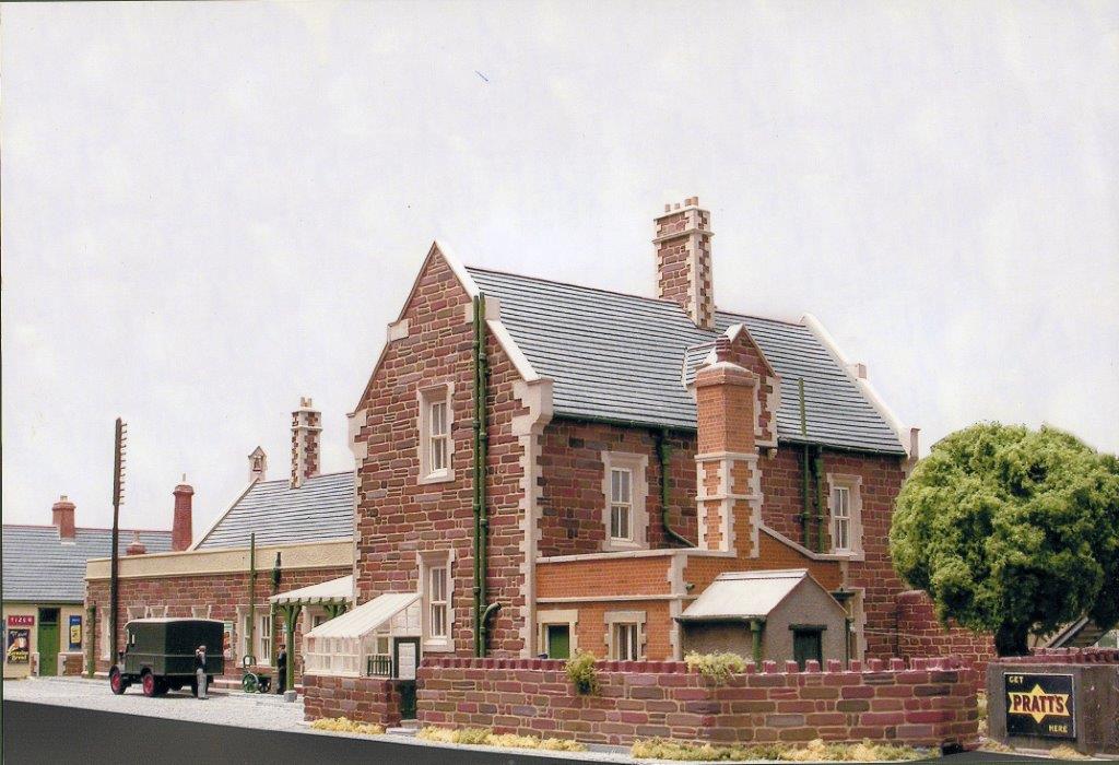 during a period of protracted illness when all I seemed able to do was read. The old railway magazines came out, rekindled my teenage interest and prompted contemplation of the construction of another layout. But where should I start?
Over several weeks the design criteria for a layout were established. It was to be OO gauge, portable and of exhibition 'quality'; set in the 1930s it would, ideally, be a through station with platforms of reasonable length; it was to be based on a prototype if possible, but not Great Western! It was to be visually interesting for spectators and operationally interesting for both spectators and operators. It also had to be capable of being viewed or operated from both sides - no 'Queen Anne front and Fanny Anne back' modelling for me! Several of these ideas came about, I have to admit, as a reaction against the plethora of GWR and other small branch line termini that seemed to dominate the model railway press and exhibition circuit around that time.
A visit to Barnstaple Junction whilst on a convalescent holiday in North Devon gave me the final inspiration that I needed. Although ostensibly in Barnstaple to do some shopping, I had shortlisted Barnstaple Junction as a potential modelling prototype beforehand - coincidentally! The visit was disappointing. No trains were seen and no longer operating as a junction station, with only a limited rail service, the station and surrounds were a shadow of the illustrations I had seen of Barnstaple in its heyday.
Nevertheless, it was a Southern Railway station with junction status and considerable operating potential, with diverging lines to llfracombe and Torrington and beyond. As such, it immediately 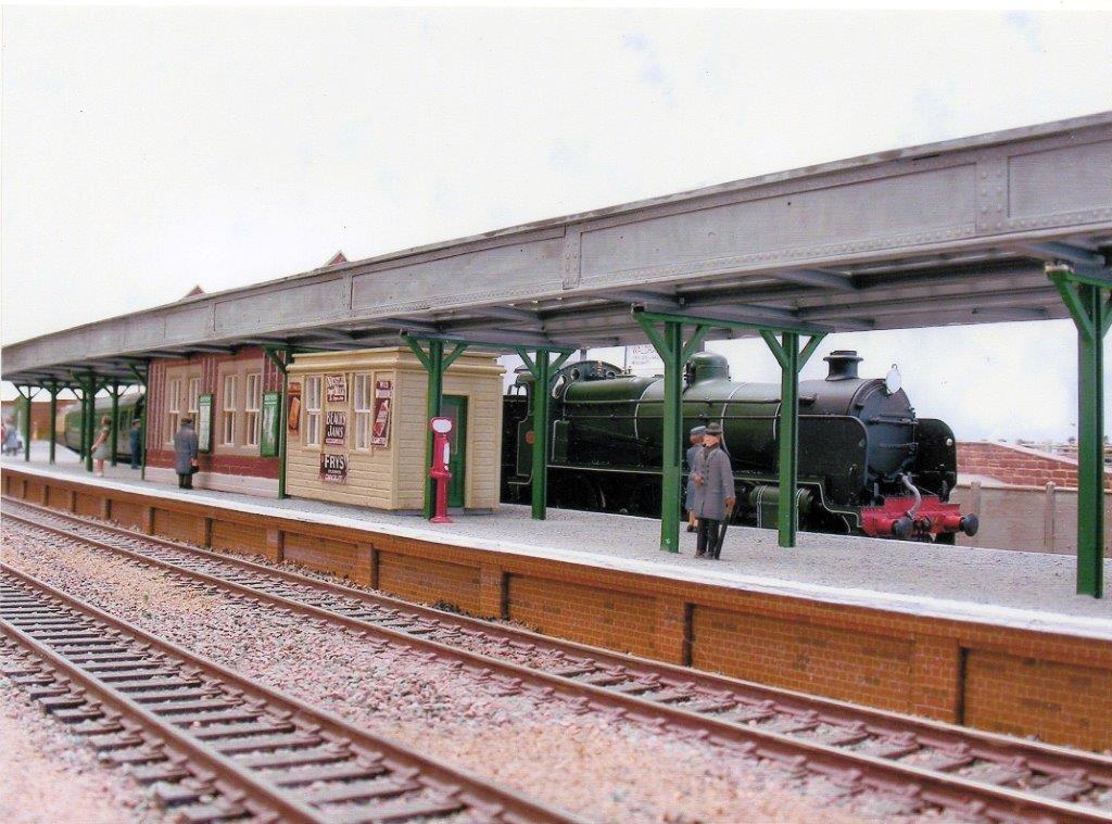
Having chosen Barnstaple Junction as the prototype to model months of research followed, continuing to this day. Copies of 1930s Ordnance Survey plans were obtained from the British Library and many hours were spent in Barnstaple's Local Studies Library and on the station itself. Copies of relevant books were acquired and endlessly referred to.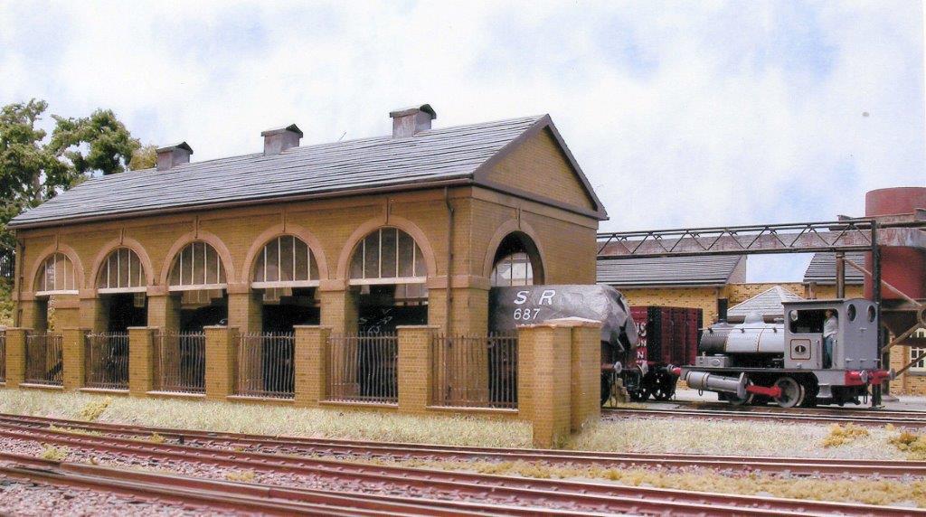
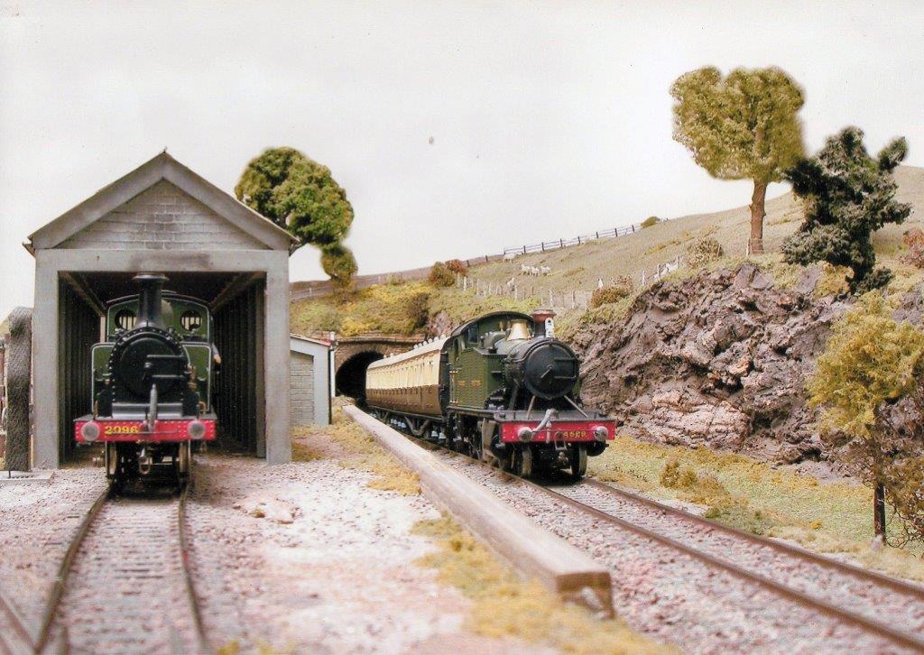
After all the research it became obvious that to reproduce Barnstaple Junction exactly was impractical. I have taken liberties, therefore, with the station layout but tried to retain its essential character. The goods yard, for example, is only partly modelled and it's on the opposite side of the station buildings to the prototype. The engine shed is modelled on that at llfracombe rather than Barnstaple, the former being the more interesting structure, and set in a 'rural' situation to increase visual interest. The paper mill is a figment of my imagination - although paper manufacture was carried out in the area - but representative of the Shapland & Petter joinery works located just outside the station limits. It was to deflect the criticism that these sorts of changes might generate that the rather 'corny' name Somweir was adopted.
Why has construction taken so long? Partly because development has been sporadic, fitted between some of the demands mentioned earlier, partly because it has been a solo effort and partly because of inexperience of the implications of some of my initial design criteria. What have I done right and where have I gone wrong? It's probably easiest to answer these questions whilst describing the layout's essential components.
Baseboard construction and portability
A through station with long platforms immediately determines the size of a layout, and also necessitates two reasonably sized fiddle yards to service it. With a junction station, and Somweir essentially has a junction at each end, you need two fiddle yards in each fiddle yard! The resultant overall size of the layout, therefore, is 9.6m long, including the fiddle yards, by 750mm wide. The 'scenic' section of the layout was originally conceived as three 2.0m long boards but has evolved into two 2.0m, one 1.4m and one 1.2m.
The freestanding fiddle yards are each 1.5m long and just about adequate for the formation of reasonable length trains. To facilitate storage and layout transportation they have been designed to also stand on end and create a storage rack. Intermediate layout support, at the hinge connected board joints, is provided by freestanding leg units.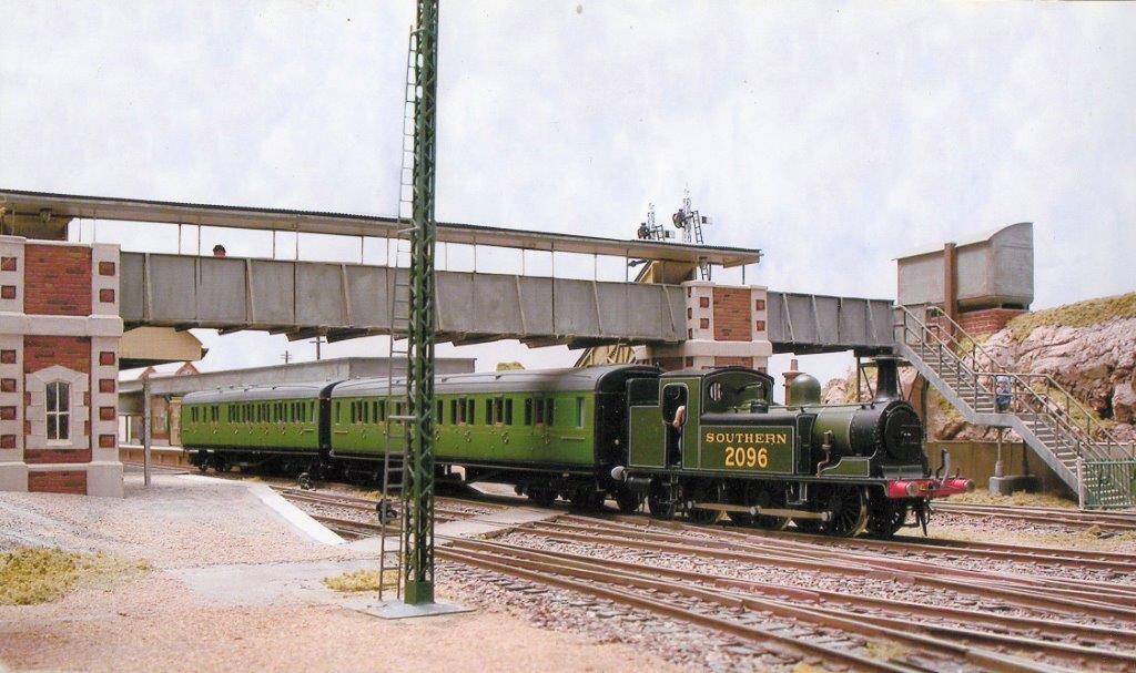
Constructed by the old technique of 13mm chipboard on 50 x 25mm softwood framing, it would be reasonable to assume that the baseboards are 'unstable', heavy and not particularly portable. They are relatively heavy but it is their size that necessitates carriage by two people rather than their weight. This form of baseboard construction has given rise to few problems over the years and two of the baseboards are at least 20 years old. This is despite the boards being stored in a garage, with the changes in ambient temperature and humidity that that entails.
Around an hour is all that is usually required to unload the van and have trains running at an exhibition, thanks to my excellent 'operators' who now know the assembly procedure and routine really well. Dismantling can be quicker. Perhaps, therefore, I have achieved the portable exhibition layout I intended. What I haven't achieved is a layout that can be fully assembled at home - two or three boards being the maximum. This causes enormous frustration in never being able to operate the layout fully other than at exhibitions, and creates considerable pre-exhibition concern over whether it will all work when fully assembled! This is despite having always 'checked-out' adjoining boards as far as possible.
Lessons learned? The boards for the next layout will be a maximum of 1.35m long, have integral legs and be capable of being fitted into an estate car or small van. Construction will be in line with current practice and the operational part of the layout will be able to be erected in the house. One final thing; the layout will be much shorter than Somweir - less track, less scenery, fewer buildings and, hopefully, speedier completion!
Wiring and control
A junction station implies wiring complications; trains have to be made up as well as split, necessitating simultaneous occupation of running lines by different locomotives; running lines cross and there have to be alternative route connections between them. With a long layout there is also potential for nothing to be happening in front of the viewing public for several minutes, whilst shunting and other manoeuvres are going on elsewhere. Anticipating the criticism that 'nothing ever happens^ Somweir has been designed to have up to four locomotives 'in steam' at any one time somewhere over the length of the layout. Whilst one is 'on shed' or being turned on the turntable, others can be shunting in the factory and goods yard, engaged in making up or splitting trains or simply arriving or departing with other trains. This flexibility is achieved by breaking the track up into a number of electrical 'sections', around 12, wired on a common return basis, and the careful siting of isolating breaks. The consequences of all of this are extensive wiring, compounded by electrically operated turnouts and interlocked signals.
With so many wires potentially flying about I have had to be extremely disciplined in my wiring methods. Spaghetti was never an option! Records have been kept of all circuits, the colour coding of individual wires and the wiring up of the multi-pin plugs between baseboards. These records have proved invaluable when changes to the layout have been made or when locating faults brought about by expansion, contraction or mechanical damage. Good record keeping and tidy under baseboard wiring are things I would commend to any serious modeller.
Almost 100 wires leave the detachable control panel, incorporating the switching for the whole layout, socket outlets for the 'Compspeed' handheld controllers, capacitor discharge unit, necessary transformers and incoming mains supply. The detachable panel facilitates control from either side and incorporates a removable/ reversible track plan, independent of any electrics. The latter has proved invaluable over the years as the track plan has been modified to simplify or improve operation in the light of experience. To further facilitate control from both sides, DPDT switches are included that can reverse the polarity of the track feeds to ensure locomotives always 'go the right way' relative to the controllers. One vital addition to the panel, in the light of a particularly bad experience, has been a 'panic switch', rendering the layout completely 'dead' in an emergency!
Originally controllers were permanently mounted within the panel. The problems trying to uncouple stock up to 3m away, requiring precise location over permanent magnets, quickly became apparent. Hand-held controllers on long trailing leads, therefore, soon replaced this arrangement - creating a problem of a different sort. Despite a revised operating sequence requiring operators to deal with movements on only one side of the control panel at any one time, this 'goes by the board' when three or four people are 'in control'. How to avoid tripping over trailing leads is a problem still to be resolved!
Trackwork
Track is Peco code 100 'Streamline' throughout. This was chosen back in the late 70s because it was then the only proprietary system readily available that also included a comprehensive range of turnouts and other items. At the time, I didn't feel that I had the time or the expertise to construct the quantity of track I was going to need. Turnouts are operated by Peco or H&M motors, incorporating switches where required. Using a capacitor discharge unit, I have found it possible to operate three or four interlocked turnouts simultaneously.
A word on the ballasting may be worthwhile, as it doesn't follow usual practice. I dislike the blandness of some ballasting that you see and so have developed my own mix of Woodland Scenics products for this purpose. This mix is further mixed with 'Cascamite' powder glue and the whole brushed into the track. Track and ballast are then sprayed with water with a drop of detergent added. The result is a fairly solid track bed which, on 3mm cork underlay, doesn't unduly amplify noise and has created few problems over the years.
Signals and signalling
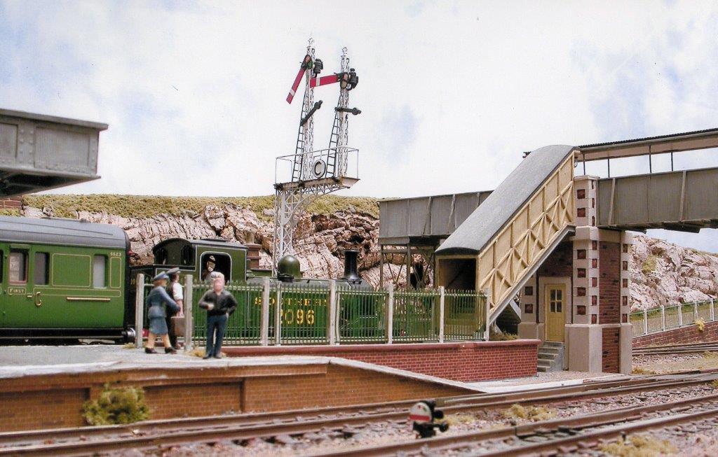
Signals are either scratch-built or made from a variety of Ratio and Sprat & Winkle (now MSE) components. However constructed they generally follow SR practice or are modelled on prototypes at Barnstaple. George Pryer's A Pictorial Record of Southern Railway Signals, published by OPC, has been invaluable in this respect.
The majority of signals have been built relatively recently, having been previously daunted by the prospect of making six lattice post bracket signals with only limited expertise. All employ angle cranks, as per the prototype, with a minimum of five or six individual connections and changes of direction per signal arm. Each connection has to be a relatively 'loose fit', the throw from the solenoid beneath the baseboard diminishing with each one. Having spent over two hours one Sunday afternoon trying to overcome this, with a signal arm still not moving, frustration got the better of me and the offending signal was hurled unceremoniously across the dining room! I am regularly reminded by the family of the day a normally patient Dad lost his cool. However, it did teach me a lesson. Several weeks later, when I set about the signal again, it was fully operational in less than half an hour. Since then, if things are going wrong I simply put the offending item to one side and try again another day.
All the signals are activated by Hornby-Dublo electrically operated signal base units, 'grafted on' to the new signal posts. This is a fairly simple process that has resulted in reliable signal operation. Although reliable, I will admit that it doesn't altogether replicate the slow rise, fall and bounce
The interlocking with turnouts mentioned earlier is basic, and requires a route to be set correctly before the relevant signal(s) can be operated. As such, it can provide a useful check for operators before sending a train on its way - but only if they remember to set the signals before moving off and reset them again once a train has passed! of the prototype!
Another form of interlocking is employed on the approaches to the Up fiddle yard. Here, unless the yard operator has made the necessary preparations to receive a train, the approach signals cannot be set and a train will automatically come to rest just before them.
The ex-Hobby Co. ground signals are non-working and have been positioned from photographs or from the signalling diagrams for Barnstaple's East and West Boxes.
Timetable/ operating sequence
To establish the train movements at Barnstaple during a typical day I compiled my own timetable, combining all the arrivals and departures on the North Devon lines and via the Barnstaple Junction Railway (GWR Loop), also noting connections with the North Devon & Cornwall Junction Railway. This was done over several weeks using the excellent OPC reprint of the SR Western Division Working Time Tables, post July 1932. Along with timetables this book also includes useful information on the composition of freight trains and classes of engines and brake vans to be used, as well as other more general instructions.
The final timetable allowed me to see, at a glance, the 'comings and goings' at the station at any time during the day. My children's reaction on seeing the completed document was that 'I should get out more'! They could have a point, but I did derive a strange satisfaction from doing it.
From the timetable it was obvious that I couldn't hope to replicate the volume of traffic at Barnstaple - around 70 arrivals and departures throughout the day. I therefore only ever run a representative one, reflecting typical passenger and freight train workings. Even this results in an operating sequence of some 40 manoeuvres, including splitting the 'Atlantic Coast Express' and attaching a GWR slip coach, slipped at Taunton from the 'Cornish Riviera Limited' to the llfracombe portion.
Scenery
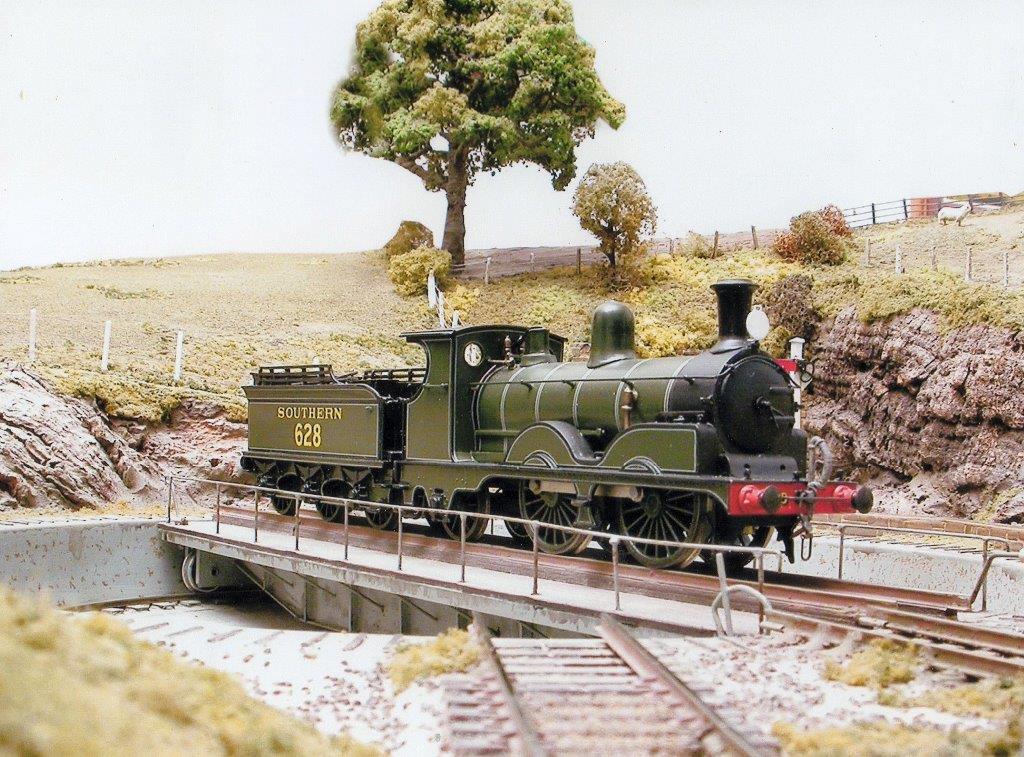
The only truly 'scenic' part of the layout is the area surrounding the engine shed and turntable. Elsewhere scenery tends to fill in the spaces between the track and edges of the baseboards! The techniques and materials used are little different to those used on other layouts. There are one or two deviations from 'normal practice' however, which prompt regular conversation at exhibitions.
The rock faces incorporated into the large hillside and located behind the island platform, for example. These are made from pieces of cork bark, purchased from either the local model shop or pet shop. They tend to be cheaper from the latter and obtainable in larger pieces. The individual pieces are fixed back to chipboard or balsa wood profiles and then to the 'ground' and each other using a proprietary filler. This is then sculpted and painted to form an appropriate transition. Time spent beforehand in trying to get some sort of match between adjacent pieces of cork aids continuity and simplifies transition formation.
The large hillside is perhaps worthy of comment. Formed from papier mache on wire netting over chipboard formers, it gave rise to a lot of problems in the early days - minor earthquakes being a regular occurrence! The problem was eventually identified as the atmospheric changes within the garage where the layout is stored, the papier mache constantly absorbing moisture and drying out. Although painted on top it was fully exposed on the underside. Several coats of spray enamel on the latter have, more or less, eradicated the problem.
Each of the Merit tunnel mouths built into the hillside, and the overbridge portals at the opposite end of the layout, incorporate a black polythene strip screen, similar in construction to the draught-proofing screens used in warehouses. The purpose of these is to create the illusion of a train disappearing 'into the distance'. It's a fairly simple device that reduces the obvious and visually apparent sight of a train just disappearing into a fiddle yard.
The river is made up of several coats of gloss varnish on a painted river bed - nothing new there. 'Pricking' of individual coats with a stiff brush, however, as they have dried, has given the river surface a natural ripple that can be clearly seen, like the real thing, more clearly in some lights than others. Finally, although trees are generally proprietary or made from twisted wire, occasionally pieces of trimmed shrub root have been used - privet is particularly good. These can produce a very delicate, self-coloured and natural representation of an ageing or distressed tree.
Locomotives and rolling stock
It is with these in particular that I was most naive in the implications of my design criteria. Firstly in the number of engines and the amount of rolling stock that satisfactory operation of the layout would require and secondly, in the implications of the chosen period. The problems facing the SR modeller in the 70s and '80s were far greater than they are today. There were few kits and proprietary items available and those that were, by today's standards, were of fairly indifferent quality. Zero confidence in my own scratch-building ability and a determination to only run stock that would have been seen in North Devon further exacerbated the problems.
 For many years a much modified Tri-ang M7, K's Adams 'Radial; BEC 700 Class, DJH 0395 and N Class, much modified Lima 'Small Prairie' and Mainline 'Collett Goods' comprised my basic locomotive stud. These just about allowed me to operate a reasonably representative timetable without too many spectators realising the unprototypical 'overworking' of some of the engines! One 'failed' engine, however, created real problems. Over the years, the stud has been extended to include another M7 (this one with a plastic card chassis!), two further N Class, a T9, E1/R, A12 'Jubilee' Class, three other GWR locomotives and Drummond's 'Bug'. Yes, the latter did traverse the North Devon rails, recorded as having failed dismally on the climb up to Mortehoe! The model, with only two driving wheels, has all the same operating characteristics as the prototype!
The number of goods wagons too has increased over the years, now standing at just over 70.1 have tried to give these, and their loads, a local 'flavour' and purpose, at the same time reflecting relative numbers of wagon types and railway company representation that existed at the time. The majority are kit-built but there are some modified proprietary wagons in use as well.
Coaches have been an ongoing problem. In setting the layout in the 1930s I completely overlooked Mr Maunsell's preferred liveries of that time. Although the construction of a coach kit did not present a particular problem, painting and lining it out with 'simulated panelling' at and above waist level did! Never graced with a steady hand, this was way outside my capabilities. Although a good selection of 1930s GWR ready-to-run coaches always seems to have been available no manufacturer has seriously attempted a Maunsell coach in Maunsell livery. It is a pity that the excellent lining on the Hornby mid-'20s SE&C Section Maunsell coaches has not been applied to more prototypical coach bodies and underframes. Although I do have a rake of Ian Kirk Maunsell coaches, their painting deficiencies, when compared to the proprietary GWR coaches I also use, are obvious. For this reason, the mainstay of my coaching stock over the years has been a rake of Bulleid coaches, beautifully scratch-built by Nigel French in the late 70s for his own exhibition layout of the time. It is this rake that I use to represent the 'Atlantic Coast Express', as this features longest on the layout whilst splitting it or making it up again as appropriate. However unprototypical the use of these coaches might be it has never generated adverse comment at exhibitions. With this in mind, and despite what I said previously about Hornby's Maunsell coaches, I have recently super-detailed a pair of these - but retaining the excellent lining - to expand my passenger train options.
The GWR stock is a mix of Airfix and Bachmann, and the slip coach comprises etched-brass sides on an old Hornby clerestory coach, the manufacturer of the etches long forgotten. SR passenger vans include a super-detailed Tri-ang utility van, the excellent Ratio 'Van B' and Parkside four-wheeled guards and luggage vans.
It would be remiss in this section not to mention how all of the rolling stock is coupled together! At the outset I opted for Sprat & Winkle couplings and have never regretted the decision. They are robust and extremely reliable, and not visually intrusive. To ensure reliability two or three very simple jigs have been constructed and used to maintain coupling hook projections and the fixing height of the 'U'-shaped coupling bars between buffers. It is a continuing delight to see the expressions on people's faces when rolling stock is magically coupled and uncoupled without the intervention of that great finger from the sky'!
Buildings and other structures
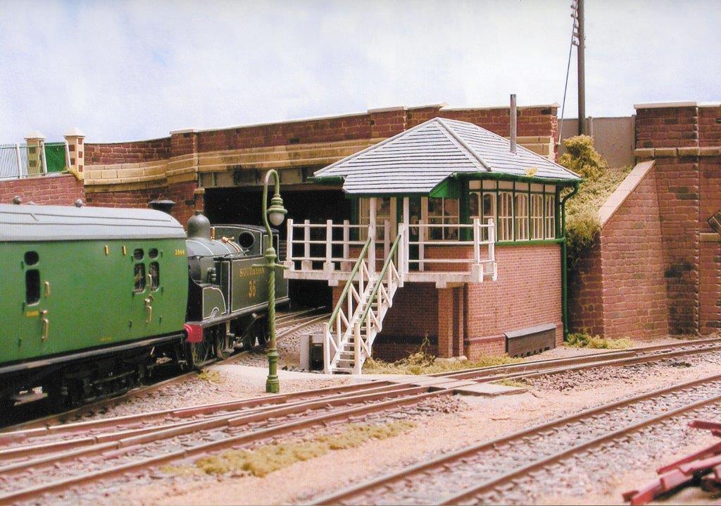
Mainly scratch-built, almost every combination of common modelling material has been used in their construction, depending on what was easiest or most appropriate. Balsa wood with an embossed plastic card facing and plain plastic card detailing form the basis of the over-bridges and retaining walls, with brick paper used instead for the masonry of the river bridges. The buildings, generally, are very different in materials used but do have other similarities; they are all built in component form and then assembled like a kit, the roofs always remaining removable to allow the later addition of interiors and lighting. I have found it easier to build windows and the like separately, on the worktop, and then insert them in to the walls of a building rather than construct them within the building itself. In so doing you are essentially working in two dimensions rather than three, and not compromised, particularly in handling, by a building's size or shape.
One advantage of opting for Barnstaple as the layout prototype was that the station building and goods shed still existed, allowing basic horizontal and some vertical dimensions to be taken. Vertical dimensions beyond my reach were determined from photographs, taken wherever possible at right angles to the relevant elevation. The hidden detail of the station roofs was gleaned from the hill overlooking the station, the other side of the island platform! The buildings and structures that had disappeared - footbridge, signal box, island platform buildings and canopy, etc, - were built from whatever photographs I could lay my hands on.
Building from photographs is not too difficult, when you bear in mind the standard sizes of building materials, the consistency of construction techniques, the standardisation employed by the railway companies in building designs and the dimensional requirements imposed by the standard loading gauge and on railway engineering works generally. Once you have the photographs, it's all about proportions and the use of a calculator. I wouldn't claim true scale models from using this technique, only models that look right.
Another reason for opting to model llfracombe rather than Barnstaple engine shed, apart from its looks as mentioned above, was the excellent photograph and drawings in OPC's An Historical Survey of Southern Sheds by Chris Hawkins and George Reeve. Reference to this will show that I have also copied the llfracombe track and turntable layouts. However, I wouldn't expect for one moment that the llfracombe turntable well is constructed from a flan baking tin - the only circular dished object I could find of an appropriate size with a hole already drilled at its centre! How you produce an operating turntable from a baking tin could form an article in itself, as could the construction of a lot of the major buildings, but would be inappropriate here. Hardly any of them have been built in one sustained effort, some taking many months to complete, overcoming the problems that have arisen and trying to retain interest and modelling standards - the 'flying signal' experience!
The 2,000 individual pieces of plastic in the island platform canopy and painting the individual stones on the station building - the only way I could achieve the colour variation of the prototype - were perfect ingredients for boredom that never crept in. Occasionally, time provided opportunities for lateral thinking. How was I to light the footbridge without wires showing everywhere? The solution adopted used the brass rainwater gutters on either side of the bridge as busbars, with connection to below the baseboard via the copper downpipes at the ends. Wiring the lamps between the gutters within the bridge roof resulted in no visible wires. How could I create the 20 individual panes of glass in each of the engine shed windows, cutting the plastic framing exactly and not getting 'Mekpak' everywhere? The solution adopted comprised fixing the mullions on one side of the 'glass' and the transomes on the other - easier to cut and glue and almost undetectable without close scrutiny.
Where buildings aren't scratch-built, Waldram & Jones lineside store is a good example, they use components from proprietary kits. In this case, the concrete panels of the Ratio Provender Store kit have been 'clad' with vertical timber boarding to produce a quite different appearance, resembling a similar store in Barnstaple's yard. Remaining panels from the kit were alternatively clad in corrugated iron to produce the smaller store adjacent to the paper mill.
Conclusions
Knowing what I know now, would I still have embarked upon Somweir's construction all those years ago? The answer has to be yes, and for a variety of reasons:
- Despite the slow progress and frustrations generated on occasions it has still provided a great deal of pleasure.
- After a rotten day at work the therapeutic effect of an hours'fiddling' has helped put things back in to perspective.
- The mistakes I've made, and continue to make, I now look upon as learning opportunities'!
- I have something lasting to show for the time and effort expended.
- Building and exhibiting the layout has taken me to places and brought me into contact with people I might otherwise have never met.
- I have produced something which brings pleasure to others and has sometimes inspired others to 'have a go' - so I have been told on more than one occasion.
It was the looks on the faces of people 'the other side of the layout' that finally got my wife 'hooked'. Although supportive throughout, over the last few years, and as the children have grown up, she has never missed an exhibition. A big thank you to her and to my operator stalwarts, Sandy Harper and John Fenton, who have also encouraged and supported me, occasionally uttering at exhibitions those calming words - 'why don't you go outside for a cigarette, have a walk around and look at the other layouts?' - and to those other operators who have also helped out on occasions. A thank you too to the 'other' John Barnes who, some years ago when progress seemed to have ground to a halt, persuaded me not to abandon Somweir.